[ad_1]
Read:
Part 1: How to get started with 3D printing in Blender
Part 2: Making and preparing 3D models for printing with Blender
In Part 1 of my series on getting started with 3D printing in Blender, I covered basic preliminary steps for getting your Blender environment set up for creating your own 3D models, ready to be 3D printed. In Part 2 I examined the process for making those models. Now let’s look at advanced tips, including metaball objects, joining objects with the fluid simulator, prepping for print, and the 3D Printing Toolbox add-on.
Metaballs and fluid simulator
It’s possible to build mesh models in an additive or subtractive way without using Blender’s Boolean modifier or either of the add-ons mentioned in Part 2 of this series. The following two techniques are a bit idiosyncratic and go back to the less precise, sculptural way of modeling, but they can be pretty handy for roughing out a base mesh that you intend on refining with sculpt tools:
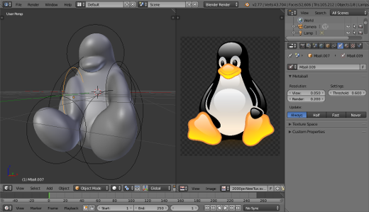
1. Metaball objects: Although I said that Blender is not a parametric modeler, Blender actually does have some parametric objects—specifically, I’m referring to Blender’s metaball objects. Metaballs are interesting and wacky things. You can add them to your scene from the Add menu (Shift + A + Metaballs). When you bring two or more of these objects close together, they start to merge, like a gloopy fluid. Metaballs are pretty old technology, but by massing a bunch of them together, you can quickly get a rough base shape for whatever you’re trying to build. Then you can just convert that to a mesh (Alt + C + Mesh from Curve/Meta/Surf/Text) and then go about refining it with Blender’s sculpt tools.

Making a rough base mesh with metaballs
2. Joining objects with the fluid simulator: Blender has an integrated fluid simulator. The unique thing about the way it works is that each animated frame of a fluid simulation is actually stored as a mesh—as geometry. This means that you can use the fluid simulator as another means of joining meshes. In practice, the result looks like using the Boolean modifier in combination with the Remesh modifier, but this technique does have the advantage of letting you combine multiple organic meshes together while also evenly distributing vertices over those shapes, without affecting those original meshes. Fair warning: Working with the fluid simulator is an advanced topic, but also is a lot of fun. You can easily find yourself distracted by the fact that you can turn your meshes into puddles of goo. In that spirit, I’ve outlined all the steps necessary to join meshes with the fluid simulator; it looks like a lot, mostly because I’m being extra-detailed. These steps also assume that your scene already has two objects in it that you’d like to join:
- In Object mode, add a cube mesh (Shift + A + Mesh/Cube).
- Scale (S) the cube so both of your objects are located within its boundary. This will be your domain object for the fluid simulator. You’ll set that up next.
- In the Physics section of the Properties Editor, left-click the Fluid button to make your cube recognized by the fluid simulator.
- In the Fluid panel that appears, use the Type drop-down menu to set your cube as a Domain.
- Select each of the objects you want to join and click the Fluid button for them as well. However, for those objects, you want to set the Type drop-down menu to Fluid.
- In Scene Properties, disable Gravity.
- In the Timeline (it’s at the bottom of the default layout), set both the Start and End frames to be 1. Because you’re using the fluid simulator as a fancy Boolean tool, you only need to have it simulate a single frame.
- With your domain object selected again, go back to Physics Properties. Set the End time in the Fluid panel to 0.000.
- Also in the Fluid panel, increase the Final resolution value. This will vary based on how detailed you need the final mesh to be. As you adjust it, you should see Blender calculate the required memory your computer will need to have in order to generate this mesh. You should probably avoid setting the Final resolution to a value that pushes the required memory above what your computer physically has.
- In the Fluid World panel, make sure the X, Y, and Z Gravity values are all set to 0.000.
- Continuing in the Fluid panel for your domain object, set the Viewport Display menu to use Final resolution instead of Preview.
- Click the Bake button at the top of the Fluid panel. Your mesh is being generated. Depending on how high you set your resolution, this could be quick, or you might need to step away and bake a potato or something.
- Once baking is complete, go to Modifier Properties, and left-click the Apply button in the Fluidsim modifier. (The modifier is added automatically when you enable Fluid from Physics Properties.)
- And you’re done—you’ve successfully joined meshes using the fluid simulator. Now you can refine it with sculpting.
Prepping for print
So you’ve got your 3D model all built in Blender and now you want to get it actually printed. Not so fast. 3D printers expect your geometry to be conditioned in particular ways. The geometry that you create in Blender—whether by sculpting, Booleans, modifiers, or even traditional vertex-pushing—isn’t typically 3D printer-friendly by default. Your model needs to have the following basic attributes:
- Manifold mesh: Basically, your mesh needs to be a completely enclosed “watertight” volume. It can’t have stray vertices or faces just floating about.
- Triangulated mesh: As I mentioned earlier in this article, most of the file formats supported by 3D printers only support triangle geometry. To that end, it’s in your best interest to triangulate your mesh from within Blender. This is easy enough to do from Edit mode. Select all of your vertices (A) and use the Triangulate operator (Ctrl + T).
- Proper sizing: Although for the 3D printer (or other software) to scale your mesh to fit the print area of the 3D printer is possible, working at the desired scale while you’re in Blender is in your best interest. Doing so makes catching other issues easier, such as small geometry and areas of your model that are too thin for the specifications of the 3D printer. If you read Part 1 and followed the steps for setting your a good 3D printing scene in Blender, you should already be good to go with this piece.
There are more detailed preparations that you may have to make depending on the 3D printer and the material that you’re printing with, but these are the raw basics. Fortunately, Blender has some tools that really help get all of these things right.
Ruler/Protractor
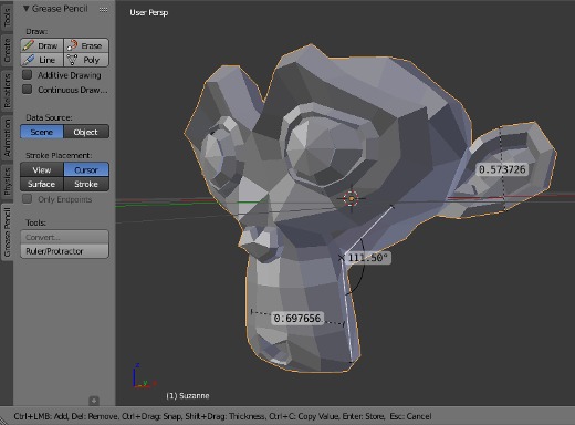
Because overly thin parts of a model can be problematic—even unprintable—for 3D printers, one of Blender’s handy built-in tools is its Ruler and Protractor. From the Tool Shelf in the 3D View, go to the Grease Pencil tab. The last button in that tab (under the label Tools) says Ruler/Protractor. Left-click that button and Blender goes into a Ruler/Protractor mode. Left-click and drag your mouse cursor in the 3D view and you can measure various parts of your mesh. Pay attention to the notes in the header at the bottom of the 3D View; all of the controls for the ruler are listed there. A quick run-down is as follows:
- Left-click + drag: Add your ruler to the scene. You can also use this to click and drag the end points of your ruler around the scene to measure different parts.
- Ctrl + Left-click + drag: Use this to add another ruler to the scene so you can see multiple measurements at the same time.
- Hold Ctrl while dragging: Snap to vertices, increments, or other elements in your 3D View.
- Hold Shift while dragging: Measure the thickness of parts of your mesh object.
- Delete: Remove a ruler.
- Esc: Leave Ruler/Protractor mode.

Measure parts of your mesh with Blender’s built-in ruler
3D printing toolbox
Another really helpful feature for preparing your models for 3D printing is the 3D Printing Toolbox add-on. This add-on ships with Blender as part of the official release, but because not everyone uses Blender for 3D printing, it’s not enabled by default. You can enable it by going to User Preferences (File | User Preferences or Ctrl + Alt + U) and searching for it in the Add-ons section.
When you enable the 3D Printing Toolbox add-on, a 3D Printing tab is added to the Tool Shelf in the 3D View. It gives you all manners of tools to check and even fix your mesh so it’s suitable for 3D printing. When you run the checks from Object mode, you get a listing of what the problem areas of your mesh might be. If you do your checks from Edit mode, you can also have Blender specifically select the vertices, edges, and faces that would give a 3D printer trouble. That lets you know exactly where they are so you can go about fixing them.
STL export
After you have everything sorted out and your mesh is ready to go, the only thing remaining is exporting it to a format that a 3D printer can use. By far, the most common format is the STL format. Blender has support for importing and exporting this format enabled by default. If you’ve enabled the 3D Printing Toolbox add-on, then there are STL export buttons conveniently located right there in your 3D View’s Tool Shelf. However, if you don’t have the 3D Printing Toolbox enabled, you can still export to STL from the File menu (File | Export | STL [.stl]).

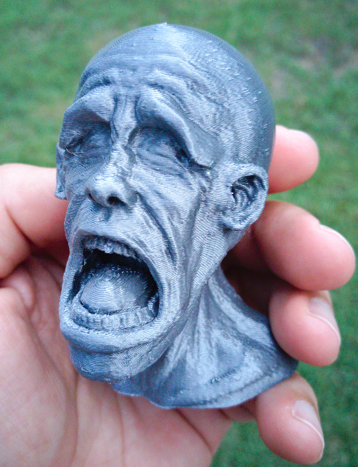
3D printed model from Blender
And that’s it! With your STL file in hand (or, in USB stick), you can get your model 3D printed. If you’re fortunate enough to have your own 3D printer, then you can go through the process outlined in your hardware’s manual. For the rest of us, there are still other options. Try visiting your local library or makerspace. A lot of libraries in larger towns have 3D printers and offer 3D printing services for reasonable prices (even free in some places). Alternatively, you could use a service like Shapeways or makexyz to pay someone else to 3D print your model and ship the finished piece to you. Either way, you’ve got the tools available to make 3D models that are ready for printing. Have fun!
[ad_2]
Source link